No products in the cart.
Arduino Due Board 32 bit ARM Cortex-M3




Roll over image to zoom in
EGP1,600.00EGP1,650.00 (-3%)
Arduino Due Board 32 bit ARM Cortex-M3
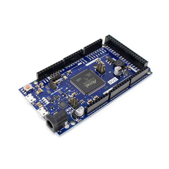
The Arduino Due Board is a powerful microcontroller board based on the 32-bit ARM Cortex-M3 CPU (Atmel SAM3X8E), designed for advanced projects requiring higher processing speed and more memory compared to traditional Arduino boards. Operating at 84 MHz, it delivers fast computation, making it suitable for real-time applications and complex tasks. The board features 54 digital input/output pins (of which 12 can be used as PWM outputs), 12 analog inputs, 4 UARTs, 2 DACs, 2 I²C interfaces, a USB OTG capability, and a CAN bus, offering wide flexibility for connectivity and control. With 512 KB flash memory and 96 KB SRAM, it provides ample space for large programs and data handling. Unlike most Arduino boards, the Due operates at 3.3V logic level, making it essential to use compatible shields and components. Ideal for robotics, automation, and data-intensive applications, the Arduino Due gives makers and engineers a robust platform to build high-performance embedded systems.
Features
Based on Atmel SAM3X8E ARM Cortex-M3 microcontroller.
32-bit architecture for higher performance compared to 8-bit boards.
84 MHz clock speed for fast processing.
512 KB Flash memory for program storage.
96 KB SRAM for data handling.
54 digital I/O pins, with 12 PWM outputs.
12 analog input channels with 12-bit resolution.
2 DAC (Digital-to-Analog Converter) outputs.
4 UART (hardware serial) ports.
2 I²C and 1 SPI interface for peripheral communication.
CAN bus interface for automotive and industrial applications.
USB OTG support for host/device functionality.
Operates at 3.3V logic level.
JTAG interface for debugging.
Compatible with most Arduino shields (3.3V compatible).
Designed for complex, data-heavy, and real-time projects.
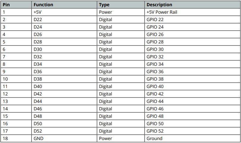
Pin Configuration
Pin Category Quantity / Label Description
Digital I/O Pins 54 (D0–D53) General-purpose I/O, 12 support PWM output
PWM Pins 12 Provide Pulse Width Modulation signals
Analog Input Pins 12 (A0–A11) 12-bit resolution analog-to-digital conversion
Analog Output Pins (DAC) 2 (DAC0, DAC1) 12-bit resolution digital-to-analog conversion
UART (Serial Ports) 4 (Serial0–Serial3) Hardware serial communication
SPI Interface SPI Header High-speed serial communication
I²C Interface 2 (SDA/SCL, pins 20 & 21) Inter-integrated communication
CAN Interface 1 (CANRX, CANTX) Automotive/industrial communication
USB Ports Programming, Native, OTG USB communication and programming
Reset Pin RESET Resets the microcontroller
Power Pins VIN, 5V, 3.3V, GND, IOREF Power supply and reference voltages
Crystal Oscillator 32.768 kHz, 12 MHz System clock source
JTAG/SWD Interface JTAG Connector Debugging and programming support
Powering the Board You can power the Arduino Due via:
USB Programming Port (connected to PC for both power and code upload).
USB Native Port (for direct communication as USB host/device).
External power supply (7–12V recommended on the VIN pin or DC barrel jack).
⚠️ Note: The Due works at 3.3V logic level. Supplying 5V to I/O pins can damage it.
Installing the Arduino IDE
Download and install the Arduino IDE (latest version).
Add Arduino SAM Boards (32-bit ARM Cortex-M3) support from the Boards Manager.
Select Arduino Due (Programming Port) or Arduino Due (Native USB Port) under Tools → Board.
Connecting the Board
Use a Micro-USB cable to connect the Due to your computer.
Choose the correct COM port in the Arduino IDE.
Uploading Your First Program
Open the Arduino IDE.
Load the classic Blink example from File → Examples → Basics → Blink.
Upload the code; the onboard LED (pin 13) should start blinking.
Using Digital and Analog Pins
Digital I/O (D0–D53): Use digitalRead() and digitalWrite() for input/output.
PWM Pins (12 available): Use analogWrite() to control LEDs, motors, etc.
Analog Inputs (A0–A11): Use analogRead() for sensor data (12-bit resolution).
DAC Outputs (DAC0 & DAC1): Use analogWrite() to generate real analog voltages.
Serial Communication
The Due has 4 hardware serial ports (Serial, Serial1, Serial2, Serial3).
Use Serial.begin(9600); to communicate with the Serial Monitor.
Using Special Interfaces
I²C (SDA/SCL): Connect multiple sensors with two wires.
SPI: Use for high-speed communication with displays, memory chips, etc.
CAN Bus: Useful for automotive and industrial systems.
USB OTG (Native Port): Can act as a USB host for keyboards, mice, or storage devices.
Programming Tips
Always double-check if your shields and sensors are 3.3V compatible.
Use the JTAG/SWD interface for debugging if needed.
Due’s 84 MHz clock speed and 96 KB SRAM allow running advanced libraries (RTOS, DSP, etc.).
Applications
Robotics systems requiring high-speed control and multiple sensor/actuator interfaces.
Industrial automation with CAN bus and real-time data handling.
IoT (Internet of Things) projects using advanced communication interfaces.
Data acquisition systems with multiple analog inputs and DAC outputs.
3D printers and CNC controllers needing precise motion control.
Wearable and biomedical devices that demand low-power, high-performance processing.
Signal processing projects such as audio effects, waveform generation, or filtering.
Educational and research projects involving embedded systems and ARM programming.
Home automation systems with advanced communication protocols.
Real-time simulation and control in scientific experiments or prototypes.